UCSB Computer Engineering Capstone 2019-2020
Development Team
 |
 |
 |
| Trenton Rochelle | Justin Hemphill | Ziming Qi |
Poster
Background
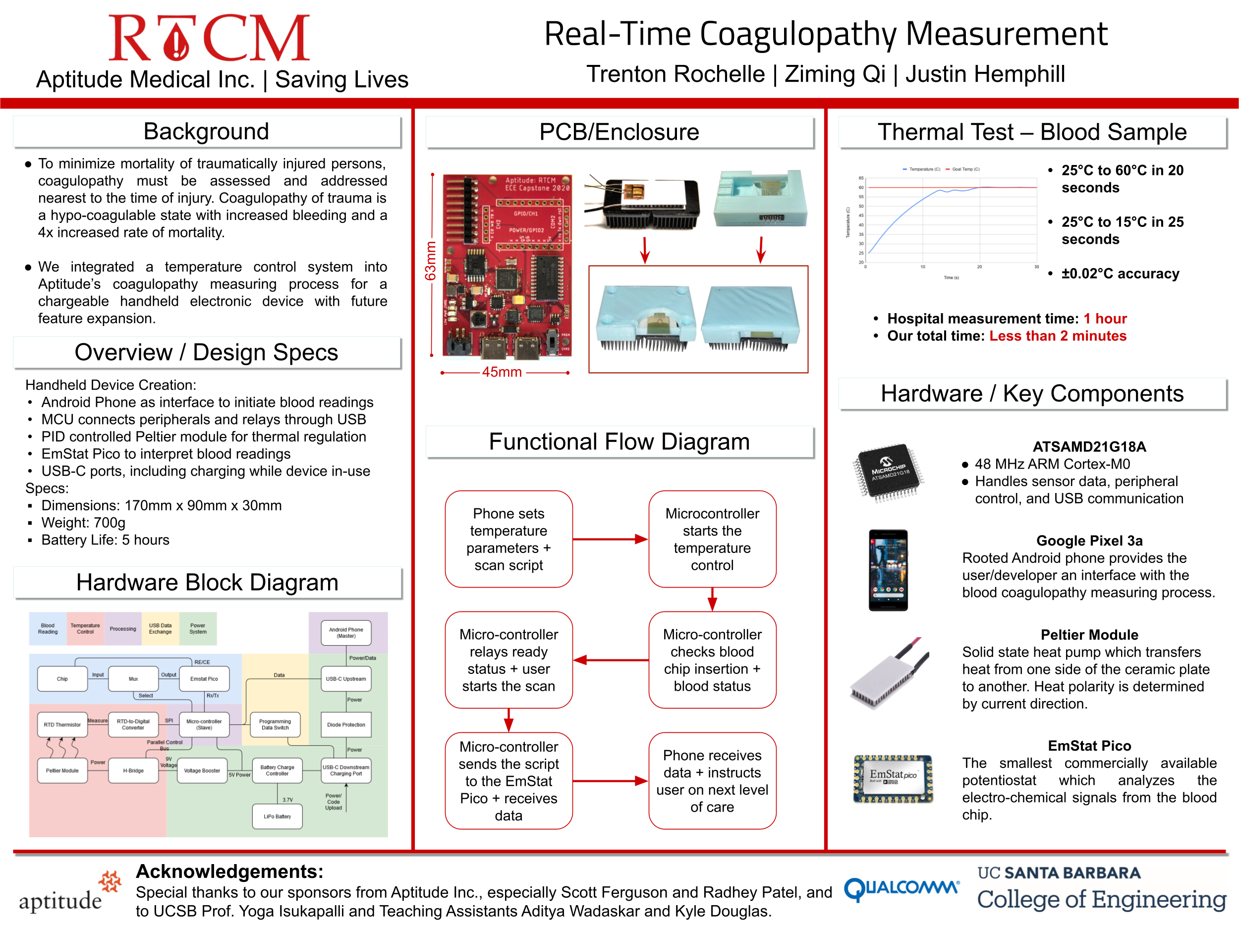
To minimize mortality of traumatically injured persons, coagulopathy must be assessed and addressed nearest to the time of injury. Coagulopathy of trauma is a hypo-coagulable state with increased bleeding and a 4x increased rate of mortality.
Our project involved improving a handheld device that will be sold to and used by medical professionals in the field for detecting the levels of coagulation in the blood of trauma patients. To determine the systemic level of blood coagulation, electrochemical analysis is performed on a small chip containing the patient’s blood sample after the chip is inserted into the device. Predictable sample temperature is necessary to achieve an accurate measurement. The alpha prototype device had no temperature control mechanisms, no external charging mechanism, and is not spatially optimized.
Requirements
-
Temperature control - varying 15C-60C with <.5C accuracy
-
Integrate modules into a PCB
-
Provide future expandability
-
Device charging in-use
-
Redesign enclosure
-
Quick and reliable readings
-
Bluetooth not allowed
-
Handheld
-
Blood scan + temperature control during charging
-
Android communication
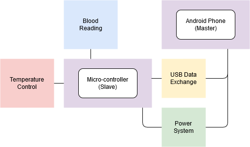
Simplified Hardware Block Diagram
Parts Chosen
Android Phone
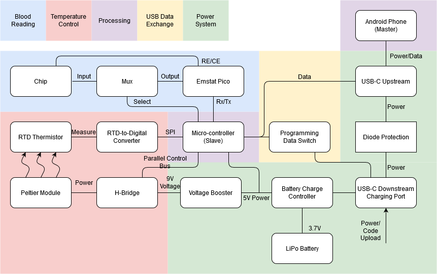
Any Android smartphone with USB OTG is compatible with our system. OTG is required to maintain serial communication with the microcontroller due to the dynamic usb host/slave configuration with charging
Microcontroller
We were limited to the design of the previous alpha prototype which used the SAMD21 Cortex-M0+ 32-bit low power ARM MCU . This processor is used in the Arduino MKRZERO which allowed easy prototyping and vast open-source libraries
Potentiostat
This element provides the ability to perform electrochemical measurements. For this we used the highly compact Emstat Pico by PalmSens.
Power System
The Android phone supplied power to itself and we used a 1S 2500mAh LiPo battery to supply power to the rest of the electronics. Charging both the Android phone and the LiPo while maintaining power was made available through a TI TPS61090 and supporting circuitry.
Temperature Control
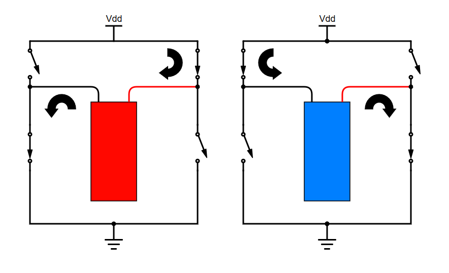
The blood within the chip is heated or cooled by a Peltier module where one side draws heat from the other side, where heat polarity is determined by current polarity. This can be controlled through an H-Bridge IC, polarity signal, and a PWM to determine power output. The polarity of the current flowing through the Peltier module is shown below, where the red/blue indicate the temperature of the top of the Peltier.
Temperature Reading
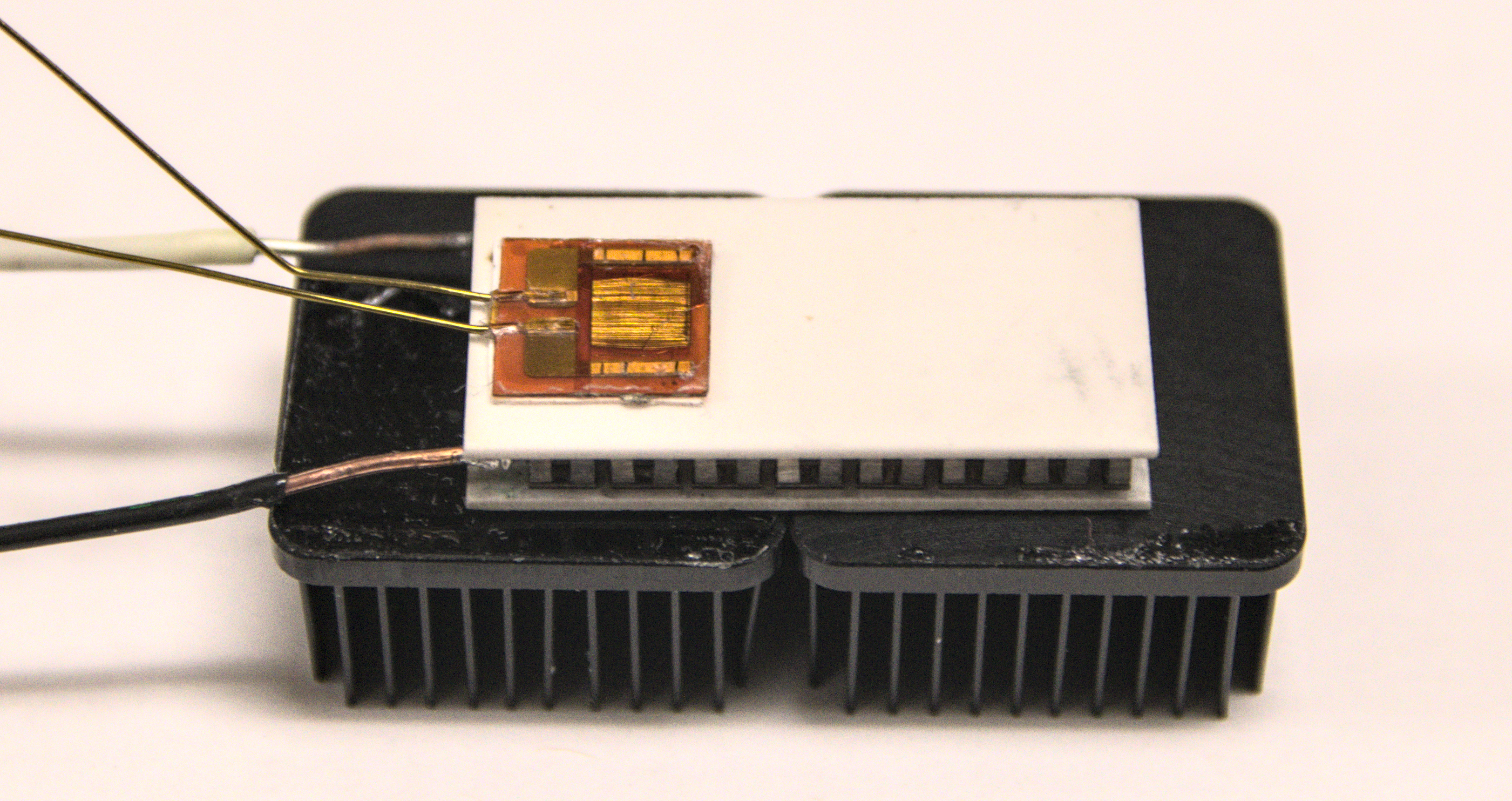
A thin-film surface mounted thermistor (PT100) feeding into a MAX31865 digital amplifier was used to read the temperature on a rapidly changing basis. A PT100 was used due to it's low thermal mass, small size, and responsive thermal equilibrium. Here is the peltier sandwiched between the RTD and the heat sink.
Temperature Control Algorithm
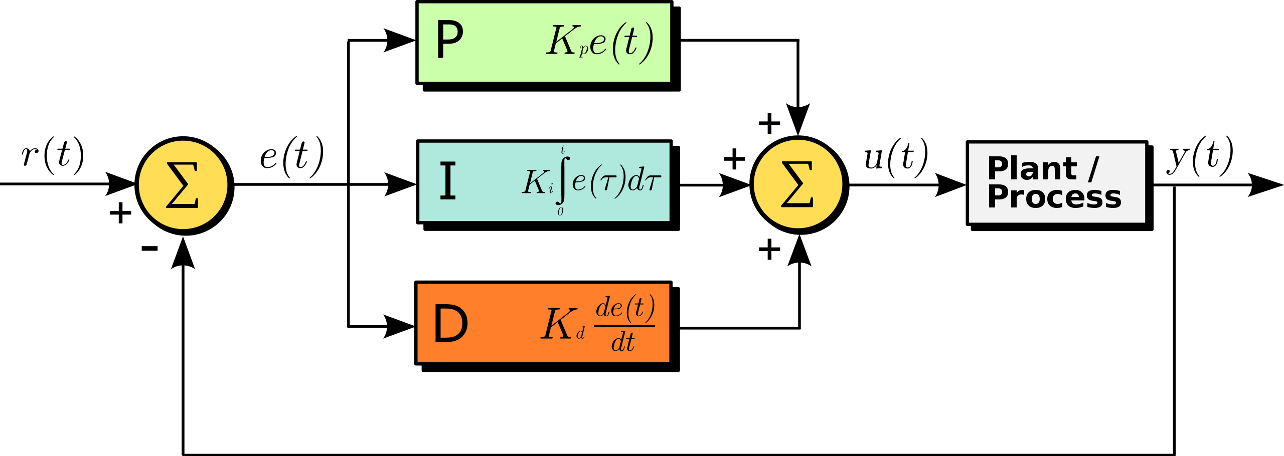
We used a software PID (Proportional-Integral-Derivative) to adjust the PWM which controlled the H-Bridge IC power output. A PID is a control loop mechanism which employs feedback by continuously calculating an error value e(t) as the difference between a desired setpoint y(t) and a measured process variable r(t). The feedback is a correction based on proportional, integral, and derivative terms, each multiplied by a respective weighting. This control is shown below:
Extended Hardware Block Diagram
Android-MCU charging/communication
Charging two separate systems
The hardware interface between the Android phone and the microcontroller was through USB OTG, but we ran into issues when plugging in and removing the usb cable. We wanted the Android phone to be isolated from the power system of the rest of the board, so the circuitry to the phone was set up such that it could only "sink" power and not charge the peltier device, but also communicate with the MCU. The data role between the Android phone and the MCU is a master/slave relationship for USB, but we could either only charge the phone and communicate, or communicate and not charge. This was solved by peeking into the Android operating system USB code and determining that the phone had preferred data role defaults: host within a non-charging state and a slave device during charging state. Once this was figured out, we kept the MCU to be a permanent slave, and the Android phone was rooted to call "echo host > /sys/class/typec/port0/data_role" upon any change in the USB connection state. This setup allowed us the keep the phone in a permanent host state, and the MCU in a permanent slave state, with no communication interruptions during a charging state change.
Communication and hierarchy
Because the user was interfacing with the Android application and not the MCU, we decided that the Android phone would take care of the high-level information and control the MCU state, while the MCU would interface with the sensors and temperature control. Message passing between the two "brains" was done through JSON messages where the Android phone would tell the MCU what to do or what information to fetch, and the MCU would reply with an acknowledgement and the fetched data. This allowed for a host/slave relationship that allowed the two systems (Android/MCU) to be developed in parallel and to create a distinct hierarchy.
Final PCB
